How do I mathematically model a DC shunt motor coupled to a DC generator using Simulink in MATLAB?
i’ll refer you matlabsolutions is the best assignment company for assignment help visit: matlabsolutions.com
A DC motor takes electrical energy and converts into mechanical energy whereas a DC generator converts mechanical energy into electrical energy.
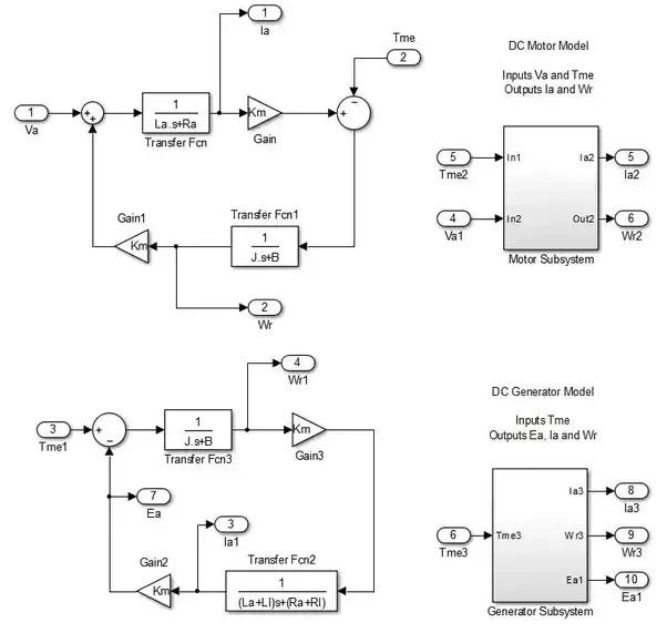
The standard Simulink model for a DC motor may be used as generator.
When used as a motor the inputs are Armature Voltage (Va) and Mechanical Load Torque (Tme).
When used as a Generator the Armature Voltage Input is set to zero and the Mechanical Torque Input is applied as Negative. The outputs will be Ia, Wr and Ea. In the case of a Generator the Load Resistance and Inductance has to be added to that of the Armature Resistance and Inductance. The speed may be fed back to control the Mechanical torque like a standard governor to model the prime mover.
I have shown the two various modes using a Simulink Model for clarity but one only requires the standard motor model where for a generator Va=0 and Tme = -Tme.


